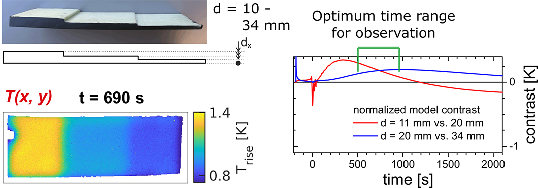
On the left side, the specimen is shown as photo and as measurement by thermography. The figure on the right side depicts the contrast within the thermal image and the choice of the optimum observation time.
Source: BAM, Division Thermographic Methods
Rotor blades of wind turbines have to withstand high loads and still need to be lightweight. Thus, the outer shell of the blades is glued with reinforcing beams. These are not visible from the outside and are accessible only to a very limited extent for damage tests. By means of thermography, the quality of the bonded beams may be checked non-destructively and faster than before – both in production or mounted on the wind turbine during the mandatory regular inspections. For the method, the surface of the rotor blade is monitored with a thermal imaging camera and heated for a view minutes, for example by the sun. After a certain time, the structure of the rotor blade becomes visible in the thermal image of its surface. A major challenge for the method is the thickness of the outer shell made of glass-fibre reinforced plastics. For a reliable inspection, a suitable long choice of the heating period and the correct observation time window for obtaining thermal images is necessary. The present publication examines how the testing person may reasonably choose the heating and the best observation time, depending on the material thickness. In addition, the publication outlines a procedure to prevent uneven heating of the surface to interfere with the measurement. The measurements were carried out using a test-specimen in the laboratory. The stiffening beam is represented in a simple way by the step form of the sample. The measurement process can be imitated by computer calculations to carry out an adapted simulation, for a more precise understanding. Finally, the simulation of the experiment enables to create tables for optimal and reliable testing for larger material thicknesses, on a production site or under outdoor conditions.
Optimizing thermographic testing of thick GFRP plates by assessing the real energy absorbed within the material
Jan P. Müller, Rainer Krankenhagen
Composite Structure, Volume 215, 2019, pages 60-68
BAM Department Non-destructive testing, Division Thermographic Methods


